Build Guides / Deep-Dive Series
Deep-Dive Series // 7 Steps

Designing Keyboard Plates & Cases

Before you can build a keyboard, you need somewhere to put the switches. This guide walks through designing a switch plate and case from scratch in OnShape — the free browser-based CAD tool we use for all MonkiiBoard designs. No prior CAD experience required, just patience and a plan.

System Status

Nominal

Difficulty

Intermediate

Build Rev.

3–5 hours

View on GitHub →

Before You Build

Gather everything below before you start — it makes the whole build go smoothly.

Component Manifest

Component Qty Specification
OnShape account Free at onshape.com — browser-based, no install
3D printer FDM printer with 0.4mm nozzle recommended
PLA filament ~100–200g PLA is easiest for plates and cases
MX switch (for fit testing) 1 Test one switch before printing the full plate
Calipers Optional but very helpful for measuring switch fit

Tools Required

01

OnShape (browser — free account)

02

3D printer slicer (PrusaSlicer, Cura, or Bambu Studio)

03

Calipers (recommended)

Build Steps

01

Step 1 // DESIGNING-PLATES-AND-CASES

Plan Your Layout

Before opening OnShape, decide your key count and grid arrangement on paper. For a grid-style macropad, note the number of rows and columns. For a staggered keyboard layout like the MonkiiBoard39, sketch the row offsets. Key spacing for MX switches is 19.05mm center-to-center — this is the number everything else is built from.

Pro Tip

Draw your layout on graph paper first — one square per key unit. It takes 5 minutes and prevents expensive reprints.
02

Step 2 // DESIGNING-PLATES-AND-CASES

Set Up Your OnShape Document

Create a free account at onshape.com and start a new document. Create a Part Studio. Set your units to millimeters in the document settings. OnShape saves automatically to the cloud so you never lose work. All MonkiiBoard files are also stored here — you can copy our documents as a starting reference.

Pro Tip

Use the OnShape keyboard shortcuts — "L" for line, "D" for dimension, "E" for extrude. They are fast once you know them.

03

Step 3 // DESIGNING-PLATES-AND-CASES

Sketch the Switch Cutouts

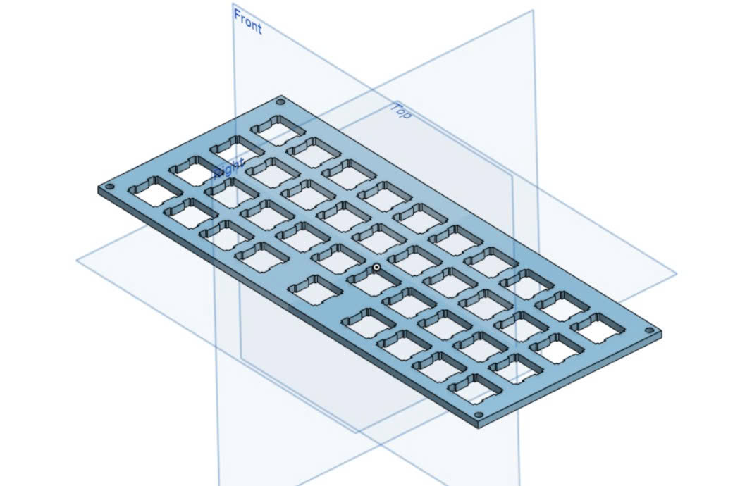
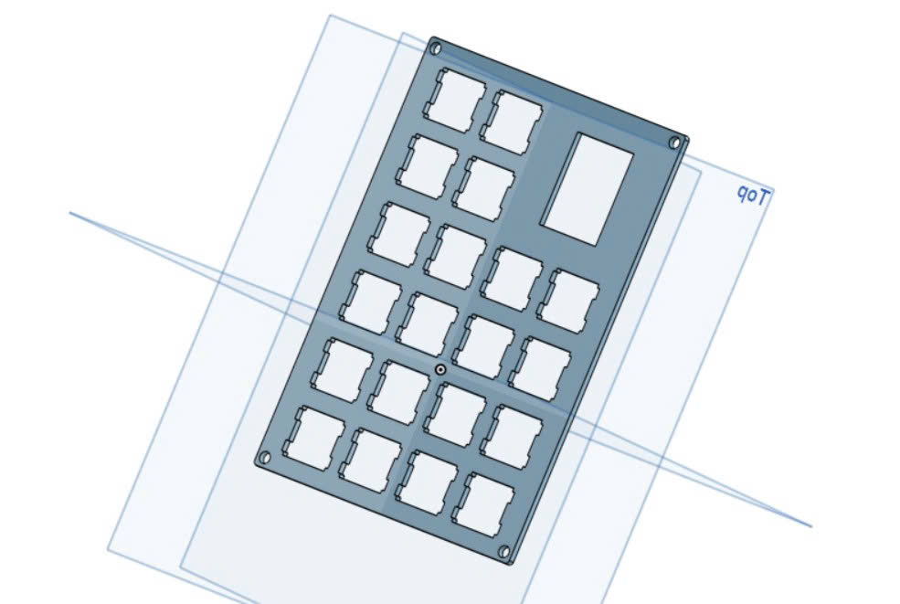
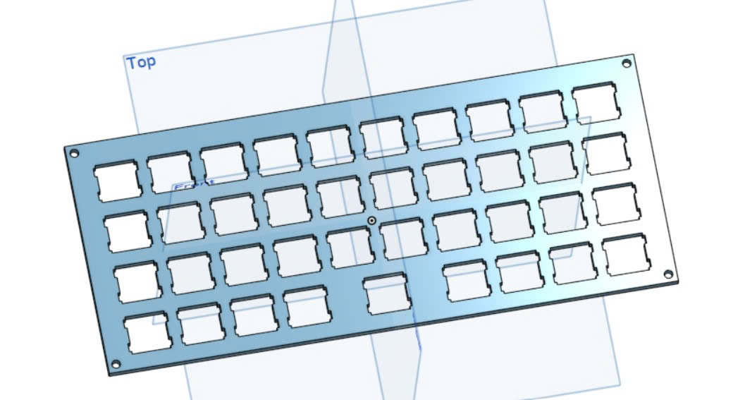
Create a new sketch on the top plane. Draw your first switch cutout: a 14mm × 14mm square centered at the origin. This is the standard MX switch hole size. Then use the Linear Pattern tool to repeat it across your row and column count, with 19.05mm spacing in both directions. Add mounting clips if needed — a 3.5mm × 1mm notch on each side of the cutout lets the switch clip in.

Pro Tip

Print a single-switch test piece first — just one cutout in a small square — to verify your switch fits snugly before committing to the full plate.

Step 3

04

Step 4 // DESIGNING-PLATES-AND-CASES

Extrude the Plate

Close the sketch and use Extrude to give the plate thickness. For a standalone switch plate, 1.5mm is the standard — this is what locks the switches in at the correct height. For a combined plate/case top, 3–4mm gives more rigidity. Extrude downward from the sketch plane.

Pro Tip

1.5mm is the MX standard plate thickness. Going thinner makes switches loose; thicker makes them hard to remove.

05

Step 5 // DESIGNING-PLATES-AND-CASES

Design the Case Body

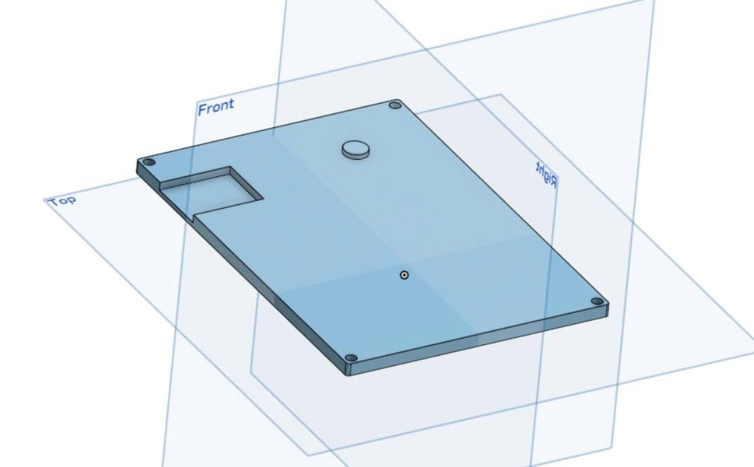
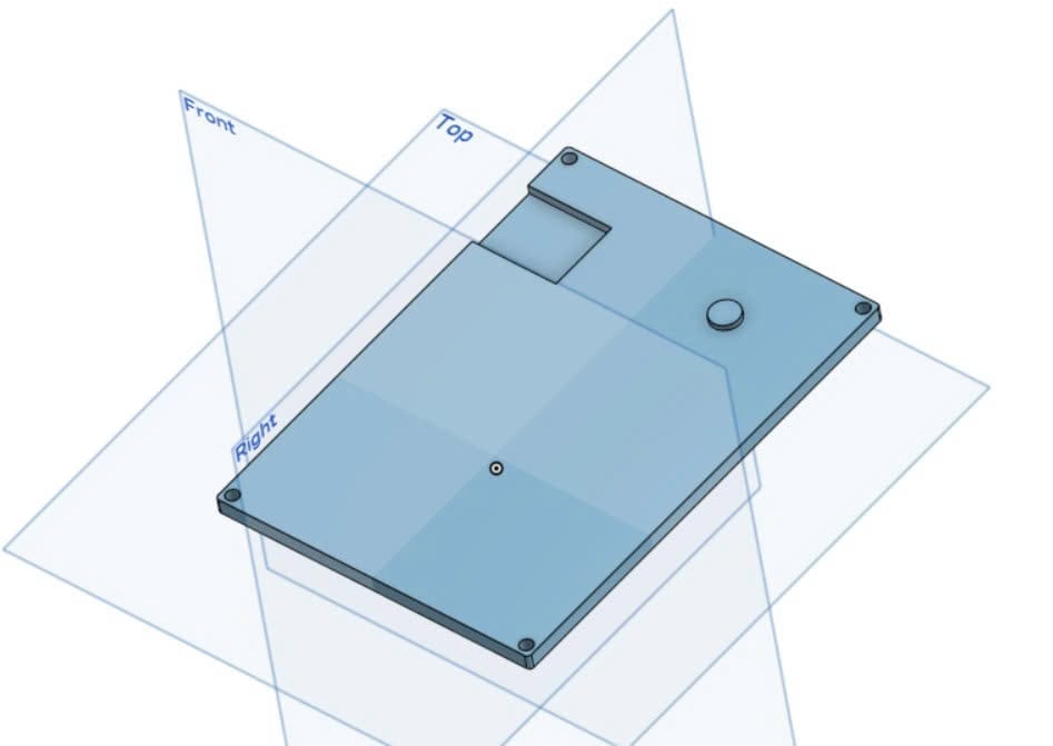
In the same Part Studio (or a new one), design the case shell. Start with a rectangle matching your plate footprint and extrude it to your desired height — typically 10–15mm for a low-profile feel. Shell the body using the Shell tool, leaving 2–3mm walls. Cut a rectangular opening in the back wall for the USB port, positioned to match the Pro Micro's port height.

Pro Tip

Leave at least 2mm of clearance above the Pro Micro inside the case — components and solder joints take up more space than you expect.

Step 5

06

Step 6 // DESIGNING-PLATES-AND-CASES

Add Mounting Features

Add M2 screw bosses to the case interior — cylindrical posts with a 2.2mm hole for the screw to self-tap into PLA. Place one in each corner and one or two in the middle for larger boards. On the plate, add matching through-holes at the same positions. This is how the plate seats and locks into the case.

Pro Tip

A 2.2mm hole self-taps cleanly with an M2 screw in PLA. No heat inserts needed for a simple build.

Step 6

07

Step 7 // DESIGNING-PLATES-AND-CASES

Export STL & Slice for Printing

Right-click each part in the OnShape part list and export as STL. Import into your slicer. For the plate: 0.2mm layer height, 40% infill, no supports. For the case: 0.2mm layer height, 20% infill, supports only if needed for the USB cutout overhang. Print the plate flat for maximum rigidity.

Pro Tip

Slice the plate with the switch-face down on the build plate — this gives the cleanest surface finish on the side that matters most.

Join the Discussion

Stuck on a step, got a tip, or finished your build? Leave us a comment through the form — we read every one and it helps us improve the guide.

Leave a Comment →