Build
Guides.
A growing pile of keyboards and macropads we built by hand, with all the files you need to make them your own. Real builds from real makers, nothing locked away.
Guides
10 available
Method
Handwired
Files
All on GitHub
Everything we make lives on GitHub and it is all free to download
Our GitHubKeymap Editor
Lay out your keys, layers and macros by clicking a matrix, then download an Arduino sketch that is ready to flash. Works for every board here, plus any matrix you wired yourself.
Browse the Builds
Every board we have documented, from a nine key macropad you can finish in an afternoon to a full thirty nine key keyboard. Parts lists, wiring, firmware and photos for each one.
How a Keyboard Comes Together
From a blank layout
to a board you built.
Every one of our builds follows the same rhythm. Here is the whole journey, start to finish, so you know what you are getting into before you open a single guide below. The per board guides fill in the exact pins, parts, and photos.
This walkthrough covers the handwired route, which is how we prototype everything. If you would rather skip the wiring, we have started printing PCBs too, and a dedicated PCB guide is on the way. Either way, every plate file, PCB design, and firmware sketch is on GitHub, free to download and free to change.
Map out your layout
Start on paper, or better yet on the Keyboard Layout Editor. Plan where every key sits in 2D before you touch anything physical. It saves you a world of trouble later.
Pick your MCU
This little chip runs the whole board. The ATMega32u4, RP2040 Zero, and full RP2040 all work great, and there are plenty of others out there. I usually reach for the RP2040 Zero because it is tiny and still plenty capable for its size.
Model your plates in OnShape
Head into OnShape and design your 3D printed files. We keep ours minimal, just a top and bottom plate with the wiring matrix sandwiched in the middle and switches and keycaps sitting on top. Screws and PLA keep it cheap, simple, and still tough. One thing to remember, carve a small rectangular hole in the bottom plate so the MCU has somewhere to sit.
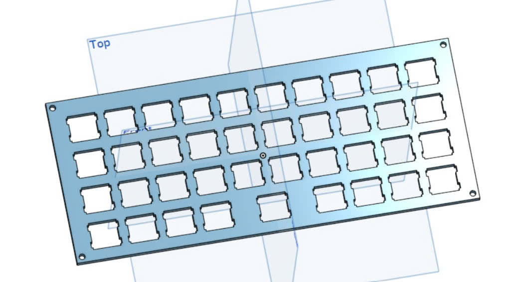
Print the whole thing
Send your plates to the printer and let them run. PLA is cheap, prints easily, and holds up just fine for a keyboard.
Mount your switches
Press the switches into the top plate and click everything into place. Give each one a wiggle to make sure it is seated flat.
Solder your diodes
Add a diode to each switch with the black tip facing the rows. Keeping them all pointed the same way is what stops your keys from ghosting.
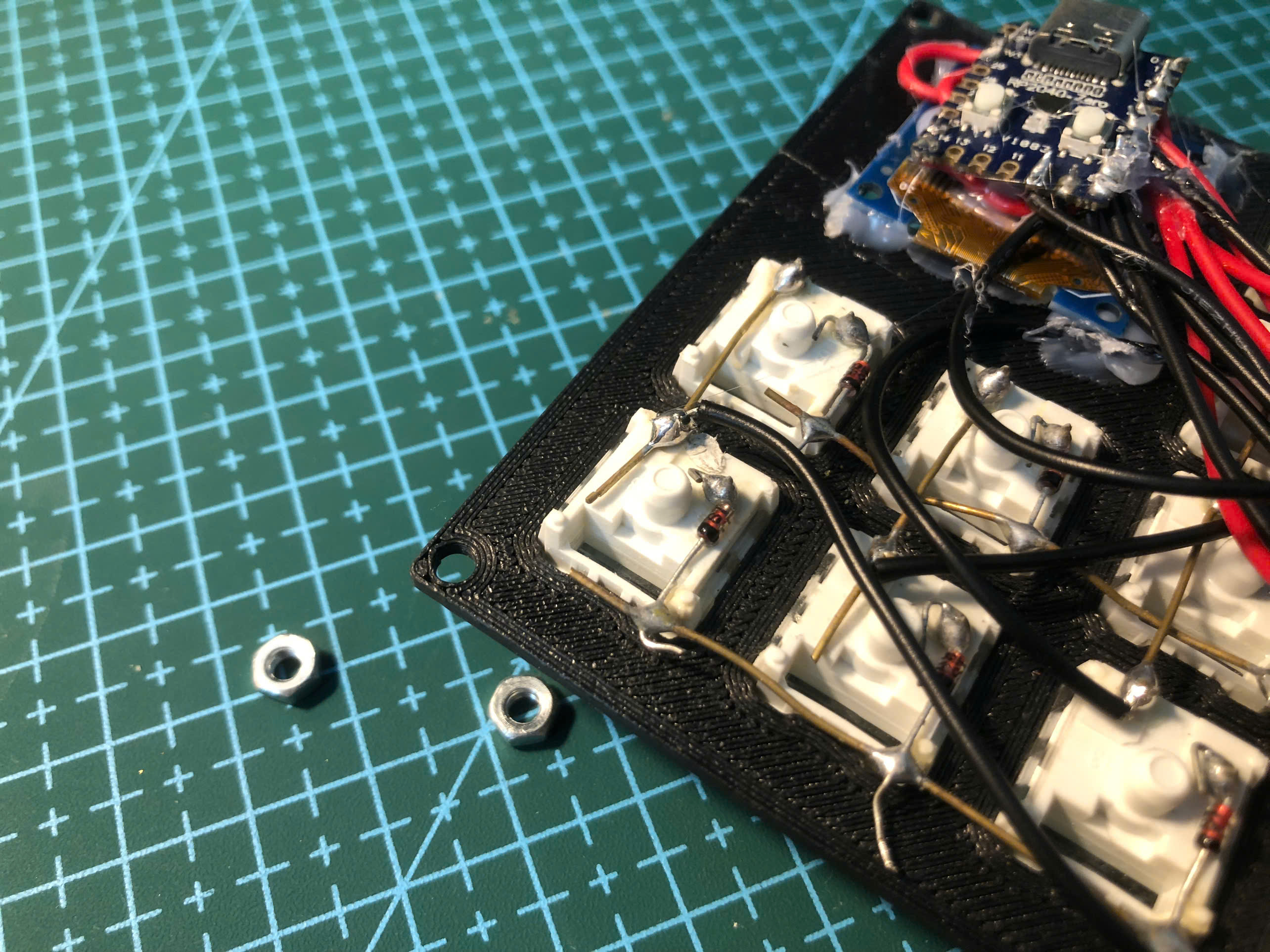
Solder your rows and columns
Run wire across the matrix, joining every switch into rows one way and columns the other. Take your time here and keep your lines tidy.
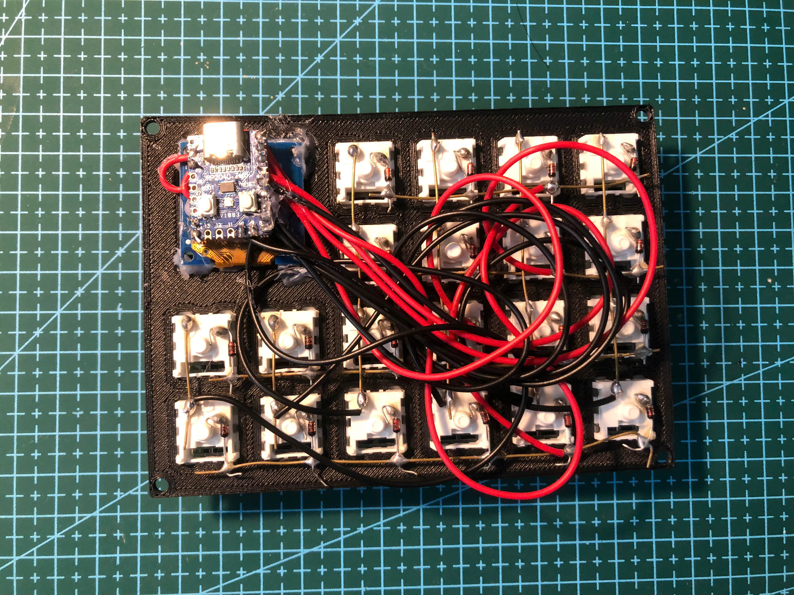
Wire into the MCU
Bring each row and column over to the microcontroller and solder them down. This is the bridge between your handwiring and your code.
Upload, debug, and test
Flash your code onto the board, then press every key and watch for the ones that misbehave. Chase down any cold joints or crossed wires until the whole matrix reads clean.
Hot glue it down
For handwired boards a little hot glue keeps everything sturdy. It is optional, but if you want your keyboard to feel permanent and firmly structured, this is the step that gets you there.
Pop on your keycaps
Snap your keycaps onto the switches. This is where it finally starts to look like a real keyboard.
Type
That is it. Plug it in and enjoy the board you built with your own two hands.
Our Latest Builds
Tested and ready to make your own
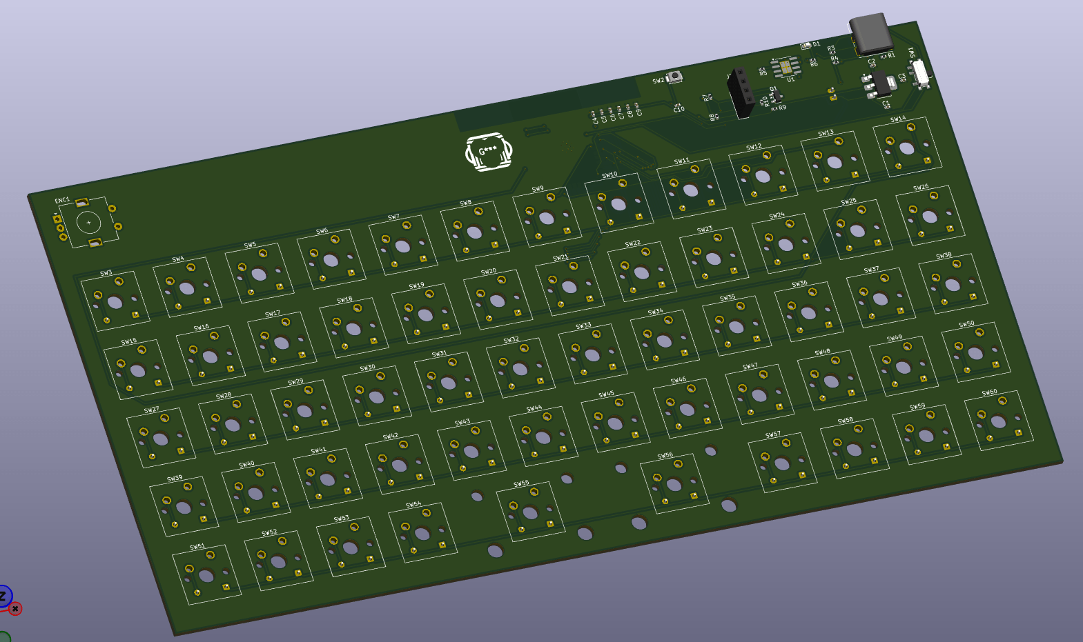
Fully documented
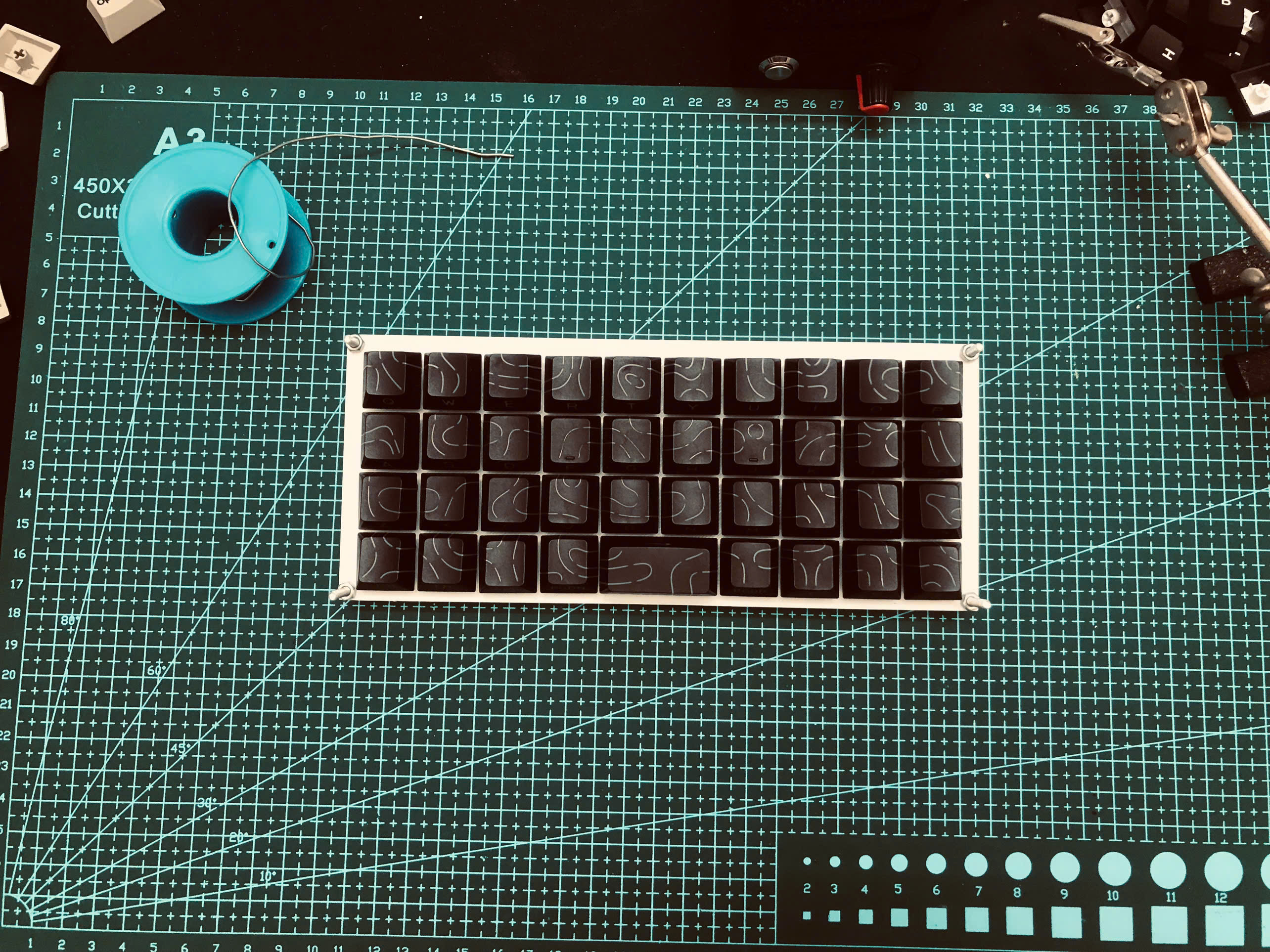
Designing the MonkiiBoard58
How we drew our first wireless keyboard, and why each part is on the board
Fully documented
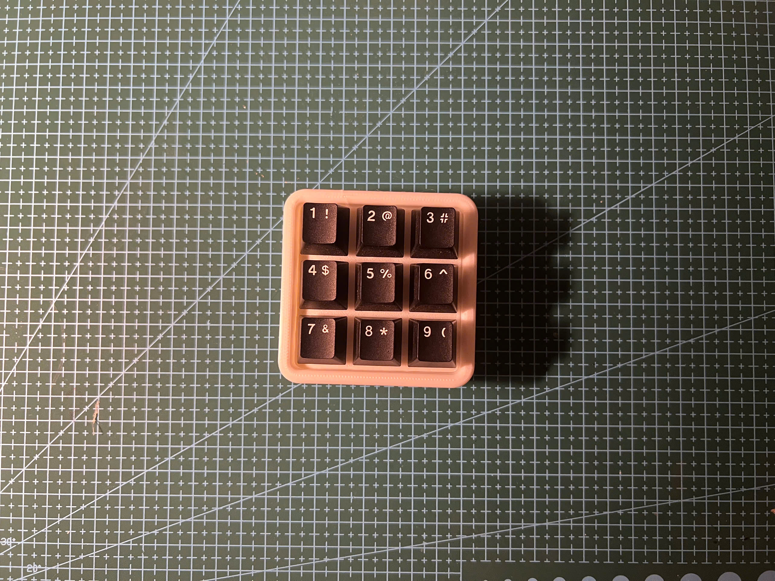
Building the MonkiiBoard39
A complete handwiring guide to building your own 39-key keyboard from scratch
Fully documented
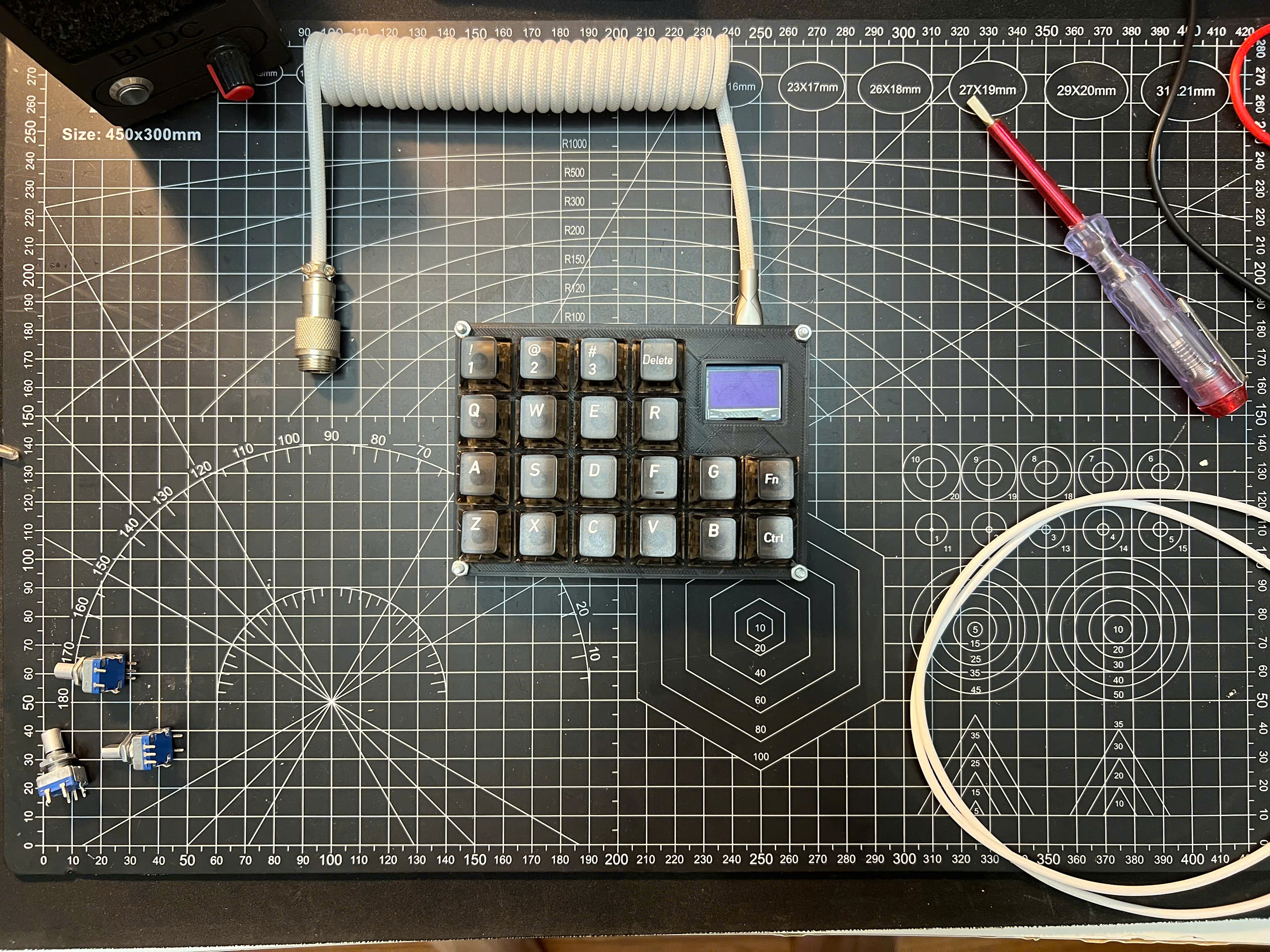
Building the MonkiiPad3x3
Build your own 9-key handwired macropad and a great first soldering project
Fully documented
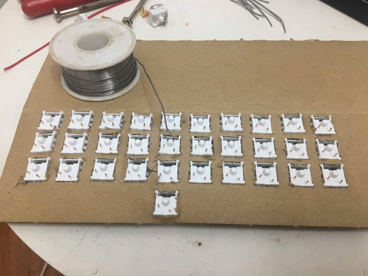
Building the MonkiiPad20
Wire up a 20-key macropad with an OLED screen on the RP2040 Zero
Fully documented
Handwiring a Custom Keyboard
No PCB required, just build a fully custom matrix from scratch
Fully documented
Designing Keyboard Plates & Cases
Model your own plate and case in OnShape, from layout all the way to a printable STL
Fully documented
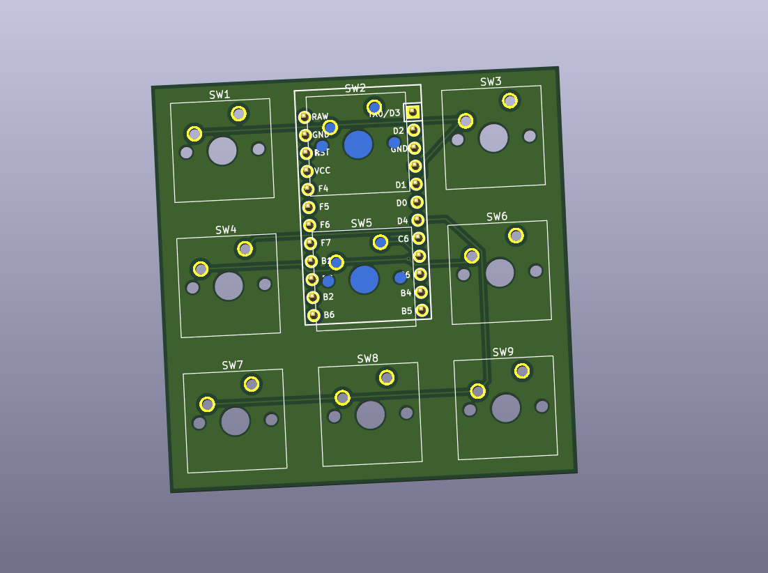
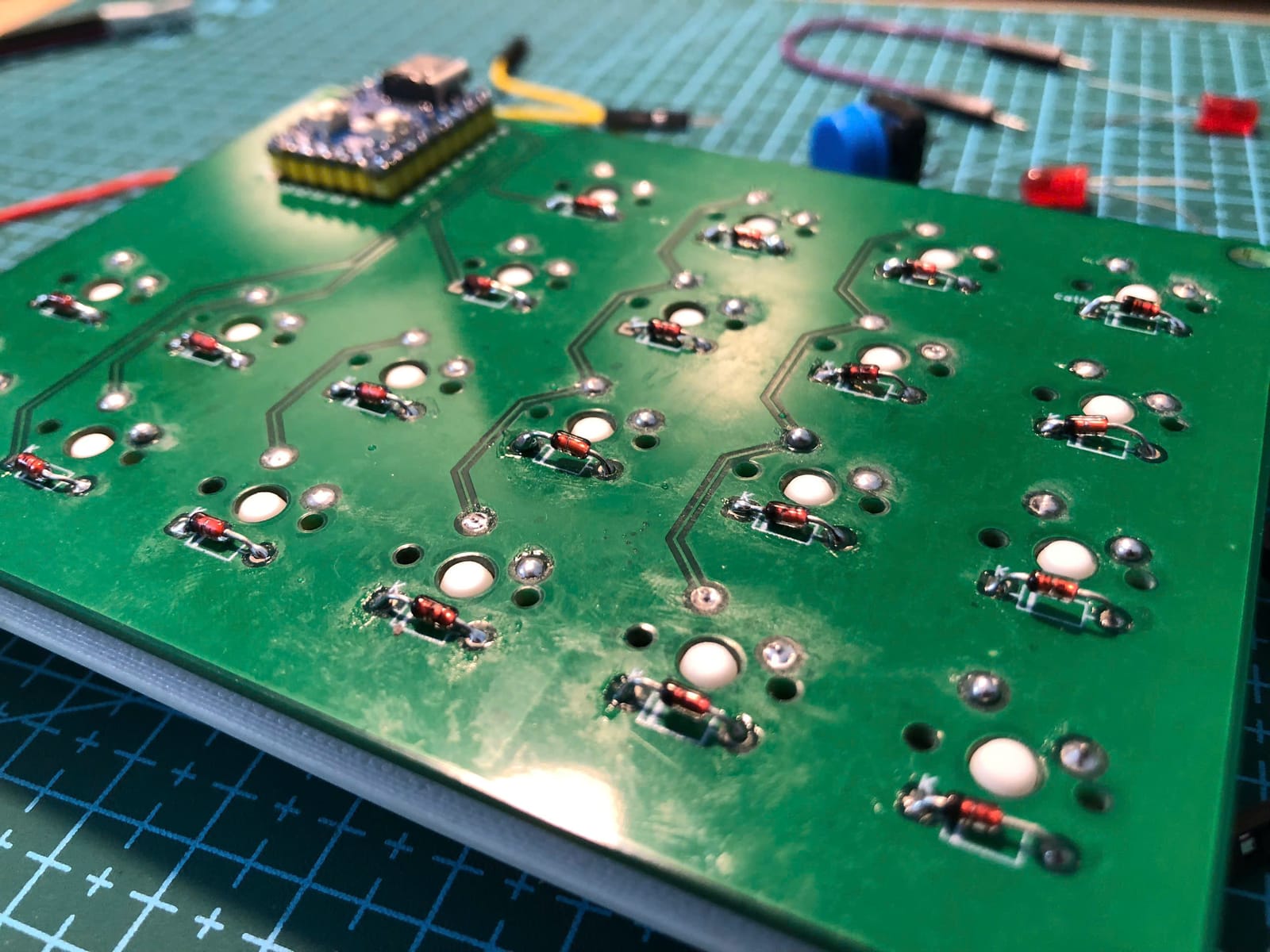
Designing a Keyboard PCB
From an empty KiCad project to files a fab house will accept
Fully documented
Soldering Without Fear
The twenty minutes of practice that makes every other guide easier
Fully documented
Flashing Your First Firmware
Getting a sketch off your screen and onto a board that types
Fully documented
Fixing a Dead Key
A short diagnostic for when one key refuses to type
Build Together.
Join the community sharing blueprints, troubleshooting circuits, and showcasing their builds.