Build Guides / Deep-Dive Series
Deep-Dive Series // 6 Steps

Building the MonkiiBoard39

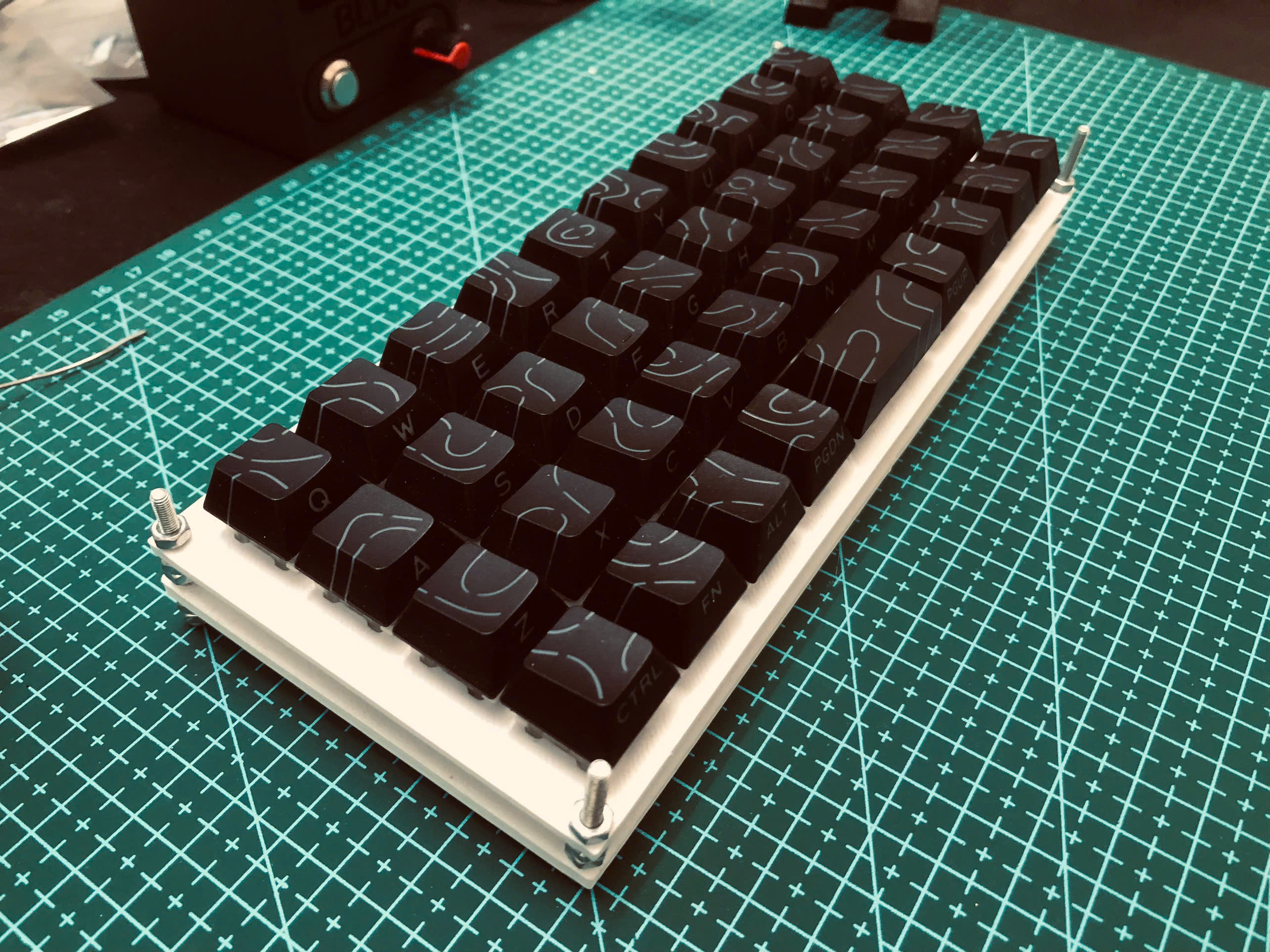
This guide walks you through every step of building the MonkiiBoard39 — from printing the plate to flashing firmware. No PCB needed. You'll handwire a 39-key matrix directly to a Pro Micro ATmega32U4, solder everything by hand, and end up with a fully custom keyboard built entirely by you.

System Status

Nominal

Difficulty

Intermediate

Build Rev.

5–8 hours

← View Product: MonkiiBoard39 View on GitHub →

Before You Build

Gather everything below before you start — it makes the whole build go smoothly.

Component Manifest

Component Qty Specification
MX-compatible switches 39 Any MX switch works — 3-pin or 5-pin
Pro Micro ATmega32U4 1 Programmed via Arduino IDE
Hookup wire (24 AWG) ~5m Use multiple colors for rows vs columns
3D Printed Plate (STL provided) 1 PLA at 0.2mm layer height, 40% infill
Keycaps 39 Any MX-compatible set with enough 1u caps
M2 screws (6mm) 6 For case assembly
Soldering iron + solder Temperature-controlled iron recommended

Tools Required

01

Soldering iron (temp-controlled preferred)

02

Solder (63/37 or 60/40 rosin core)

03

Wire strippers

04

Flush cutters

05

Multimeter (continuity mode)

06

Tweezers

07

Computer with Arduino IDE installed

Build Steps

01

Step 1 // MONKIIBOARD-39

Print the Plate

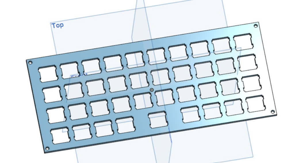
Download the plate STL from our GitHub and 3D print it in PLA. Use 0.2mm layer height and 40% infill — the plate needs to be rigid. No supports required if printed flat. The plate holds all 39 switches and forms the structural backbone of the keyboard.

Pro Tip

A textured PEI build plate gives the bottom a nice grip texture.

Step 1

02

Step 2 // MONKIIBOARD-39

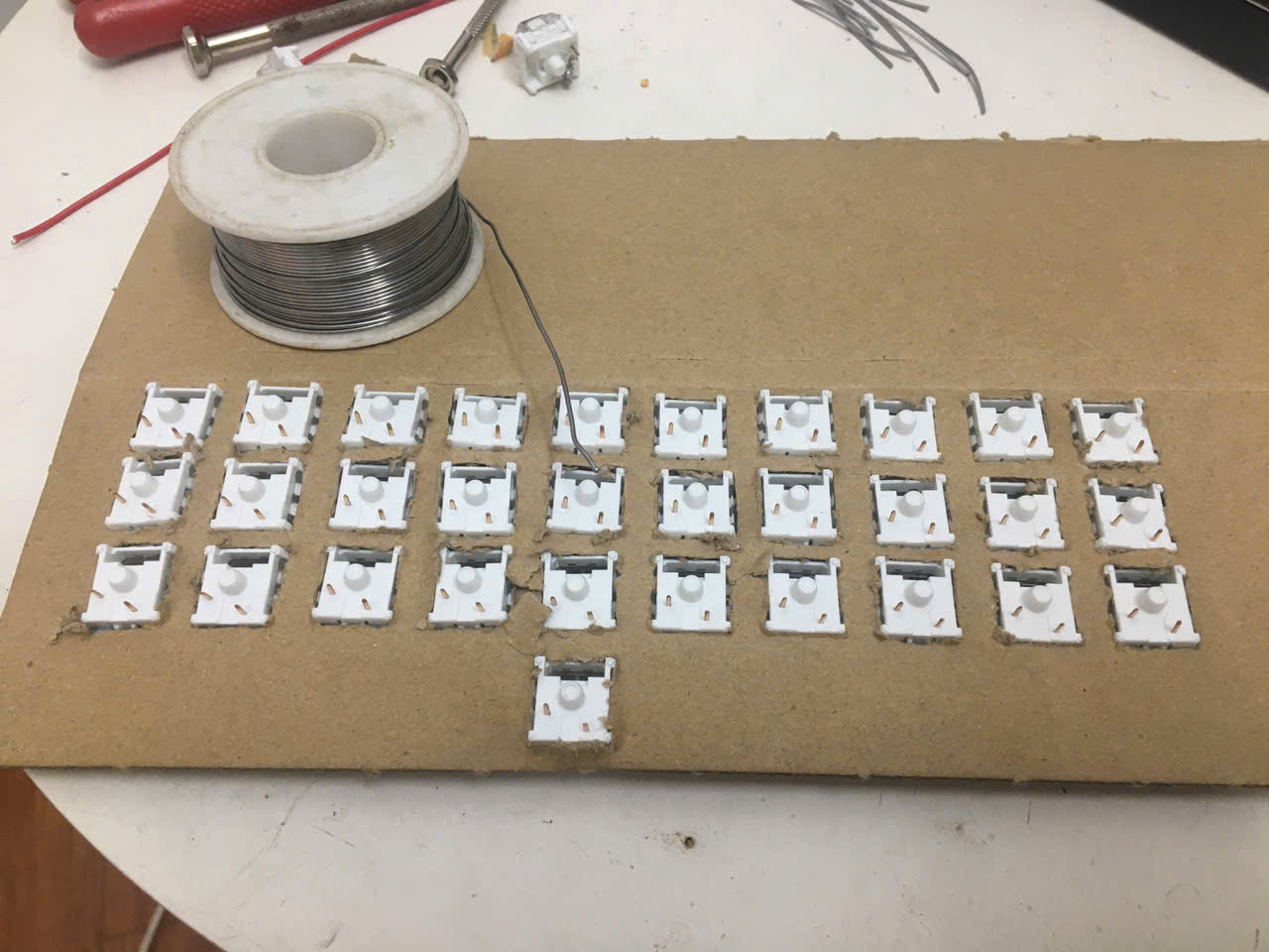
Mount Switches in the Plate

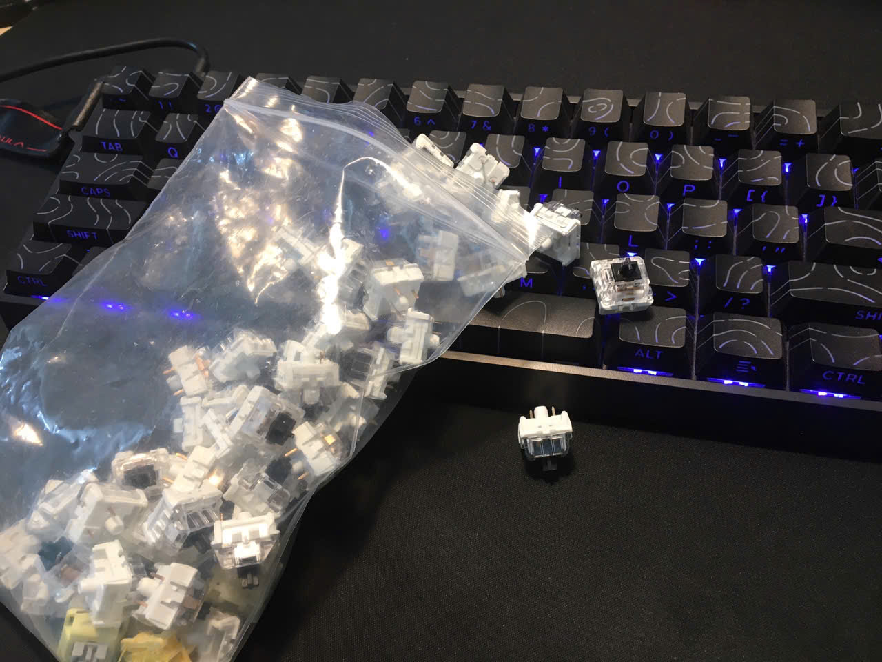
Snap all 39 switches into the plate. They should click in firmly with no wobble. Start with the four corners to lock the plate flat, then fill in the rest row by row. This is your last chance to finalize the layout before wiring begins.

Pro Tip

Check that no switch pins are bent before pressing down — bent pins cause hard-to-diagnose matrix issues later.

Step 2

03

Step 3 // MONKIIBOARD-39

Wire the Rows

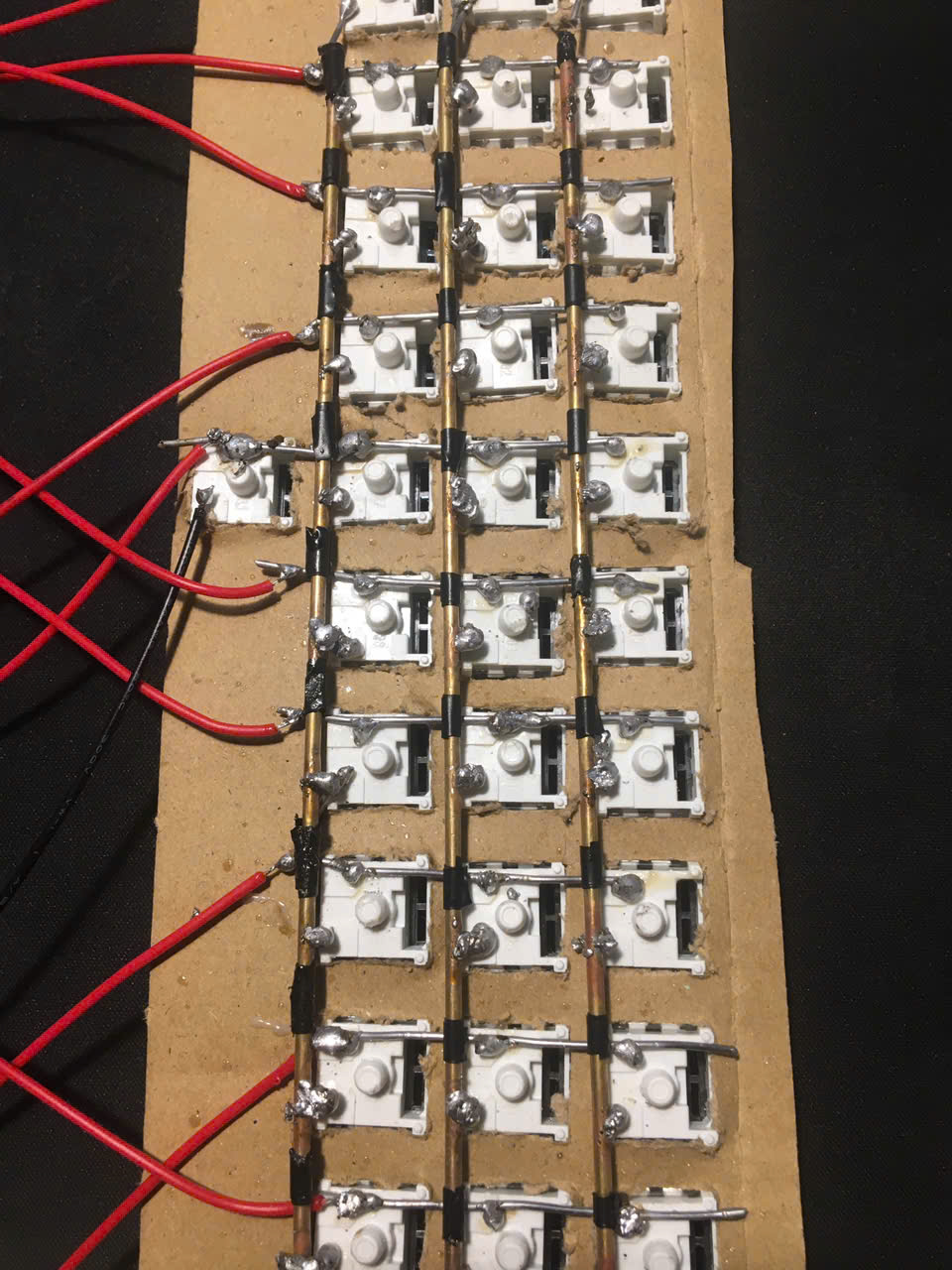
The MonkiiBoard39 is a diodeless matrix — there are no diodes to solder. Run a wire horizontally across each of the 4 rows, soldering it directly to one pin of every switch in that row. One continuous wire per row is fine: strip a small window at each switch, solder, and continue. Keep the wires tidy and flat against the plate.

Pro Tip

Use one wire color for all rows and a different color for all columns — it keeps the matrix easy to follow.

Step 3

04

Step 4 // MONKIIBOARD-39

Wire the Columns

Run a wire vertically down each of the 10 columns, soldering to the other pin of each switch. Every switch now bridges one row wire and one column wire. Row wires and column wires must never touch each other directly — only through a switch.

Pro Tip

With no diodes, pressing 3+ keys that form a rectangle in the matrix can ghost. Normal typing is unaffected — just keep it in mind for heavy chording.

Step 4

05

Step 5 // MONKIIBOARD-39

Connect the Matrix to the Pro Micro

Wire each row and column to a GPIO pin on the Pro Micro. The reference firmware uses rows on pins 2, 3, 4, 5 and columns on 6, 7, 8, 9, A1, A0, 15, 14, 16, 10. Write down every connection — you'll need this exact mapping in the Arduino sketch, or edit rowPins/colPins to match your own wiring.

Pro Tip

A simple sketch or spreadsheet of your pin mapping saves a lot of debugging time.

Step 5

06

Step 6 // MONKIIBOARD-39

Flash Arduino Firmware & Test

Open the MonkiiBoard39 firmware sketch in the Arduino IDE. Make sure rowPins and colPins match your wiring, then upload to the Pro Micro (ATmega32U4). Open a keyboard tester and press every key — all should register. Any silent key usually means a cold solder joint or a wire on the wrong pin.

Pro Tip

In the firmware, rows are OUTPUTs and columns are INPUT_PULLUP — if a whole row or column is dead, check that pin first.

Step 6

Firmware

The full Arduino sketch for this build. Open it in the Arduino IDE, match the pins to your wiring, and upload — or grab the whole repo from GitHub.

MonkiiBoard39.ino
#include <Keyboard.h>

const int colPins[10] = {6, 7, 8, 9, A1, A0, 15, 14, 16, 10};
const int rowPins[4]  = {2, 3, 4, 5};

// ===== Key state + debounce =====
bool keyState[4][10] = {false};
unsigned long lastChangeTime[4][10] = {0};
const int debounceDelay = 30;

// ===== Sticky modifiers =====
bool ctrlActive = false;
bool shiftActive = false;
bool altActive = false;
bool guiActive = false;

// ===== Double-tap GUI =====
unsigned long lastGuiPressTime = 0;
const int doubleTapDelay = 300;

// ===== KEYMAP =====
uint8_t keymap[4][10] = {

  {'q','w','e','r','t','y','u','i','o','p'},
  {'a','s','d','f','g','h','j','k','l', KEY_BACKSPACE},
  {'z','x','c','v','b','n','m',',','.', KEY_RETURN},

  // Bottom row handled manually
  {0,0,0,0,0,' ',' ',0,0,0}
};

void setup() {

  for (int c = 0; c < 10; c++) {
    pinMode(colPins[c], INPUT_PULLUP);
  }

  for (int r = 0; r < 4; r++) {
    pinMode(rowPins[r], OUTPUT);
    digitalWrite(rowPins[r], HIGH);
  }

  Keyboard.begin();
}

void applyModifiers() {
  if (ctrlActive)  Keyboard.press(KEY_LEFT_CTRL);
  if (shiftActive) Keyboard.press(KEY_LEFT_SHIFT);
  if (altActive)   Keyboard.press(KEY_LEFT_ALT);
  if (guiActive)   Keyboard.press(KEY_LEFT_GUI);
}

void releaseModifiers() {
  if (ctrlActive)  Keyboard.release(KEY_LEFT_CTRL);
  if (shiftActive) Keyboard.release(KEY_LEFT_SHIFT);
  if (altActive)   Keyboard.release(KEY_LEFT_ALT);
  if (guiActive)   Keyboard.release(KEY_LEFT_GUI);
}

void clearModifiers() {
  ctrlActive = false;
  shiftActive = false;
  altActive = false;
  guiActive = false;
}

void loop() {

  for (int r = 0; r < 4; r++) {

    digitalWrite(rowPins[r], LOW);
    delayMicroseconds(30);

    for (int c = 0; c < 10; c++) {

      bool reading = (digitalRead(colPins[c]) == LOW);

      // ===== DEBOUNCE + STATE CHANGE =====
      if (reading != keyState[r][c] &&
          millis() - lastChangeTime[r][c] > debounceDelay) {

        lastChangeTime[r][c] = millis();
        keyState[r][c] = reading;

        // ===== KEY PRESSED =====
        if (reading) {

          // ----- Bottom row -----
          if (r == 3) {

            if (c == 0) ctrlActive = true;
            else if (c == 1) shiftActive = true;
            else if (c == 2) altActive = true;

            // ===== WINDOWS KEY WITH DOUBLE TAP =====
            else if (c == 3) {

              unsigned long now = millis();

              if (now - lastGuiPressTime < doubleTapDelay) {
                // double tap → open start menu
                Keyboard.press(KEY_LEFT_GUI);
                delay(50);
                Keyboard.release(KEY_LEFT_GUI);
                guiActive = false;
              } else {
                guiActive = true;
              }

              lastGuiPressTime = now;
            }

            // SPACE (shared)
            else if (c == 5 || c == 6) {
              Keyboard.press(' ');
            }

            continue;
          }

          // ----- Normal keys -----
          uint8_t key = keymap[r][c];

          if (key != 0) {
            applyModifiers();
            Keyboard.press(key);
          }
        }

        // ===== KEY RELEASED =====
        else {

          if (r == 3) {

            if (c == 5 || c == 6) {
              Keyboard.release(' ');
            }

            continue;
          }

          uint8_t key = keymap[r][c];

          if (key != 0) {
            Keyboard.release(key);
            releaseModifiers();
            clearModifiers();
          }
        }
      }
    }

    digitalWrite(rowPins[r], HIGH);
  }
}
Join the Discussion

Stuck on a step, got a tip, or finished your build? Leave us a comment through the form — we read every one and it helps us improve the guide.

Leave a Comment →