Build Guides / Deep-Dive Series
Deep-Dive Series // 6 Steps

Handwiring a Custom Keyboard

Handwiring is the purest form of custom keyboard building. With no PCB, you wire each switch directly to a controller using a diode matrix. It takes more time than a PCB build, but gives you complete freedom — any layout, any controller, any case. If you can imagine it, you can build it.

System Status

Nominal

Difficulty

Advanced

Build Rev.

6–10 hours

View on GitHub →

Before You Build

Gather everything below before you start — it makes the whole build go smoothly.

Component Manifest

Component Qty Specification
MX-compatible switches Per layout Any MX switch works
Pro Micro ATmega32U4 1 Programmed via Arduino IDE
1N4148 diodes 1 per switch Through-hole diodes
Hookup wire (24 AWG) ~5m Multiple colors strongly recommended
Case or plate 1 3D printed, laser cut, or custom-made

Tools Required

01

Soldering iron

02

Solder

03

Wire strippers

04

Flush cutters

05

Multimeter (continuity mode)

Build Steps

01

Step 1 // HANDWIRING

Mount Switches in Case

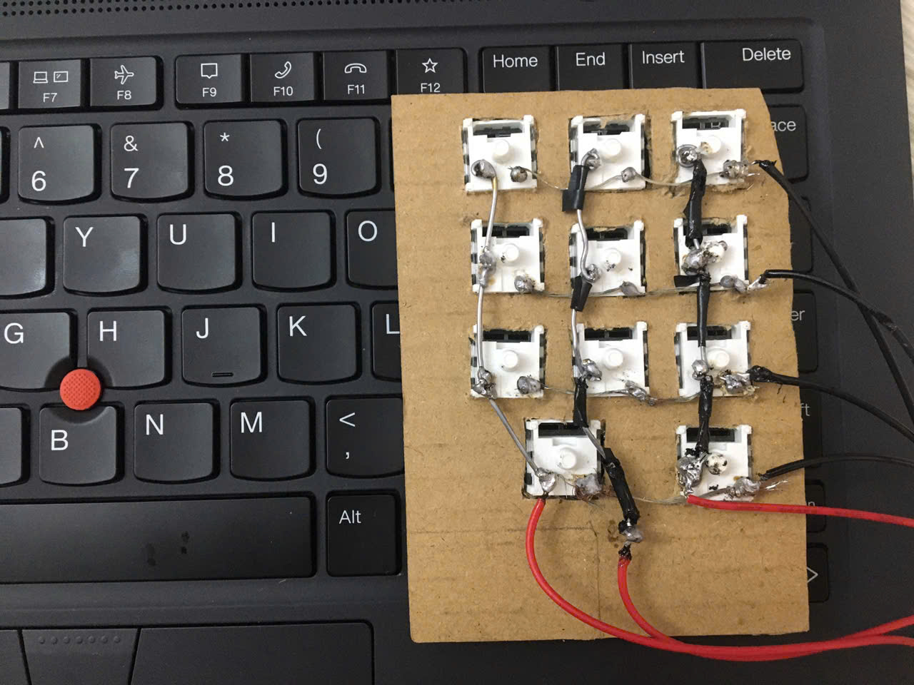
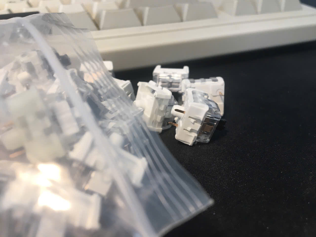
Mount all switches in your plate or case. They should snap in firmly with a click. This is your last chance to finalize the layout — take your time and make sure every position is correct before wiring.

Pro Tip

Sketch your layout on paper and number rows/columns before you start wiring.
Step 1

02

Step 2 // HANDWIRING

Solder Row Diodes

Solder one 1N4148 diode to the bottom pin of each switch. The cathode (black stripe) must point toward the row wire — consistent direction on every switch. Bend the diode body close to the pin, solder, and clip the excess lead.

Pro Tip

Wrong diode direction on even one switch will make a whole row ghost — check every stripe before soldering.

Step 2

03

Step 3 // HANDWIRING

Wire the Rows

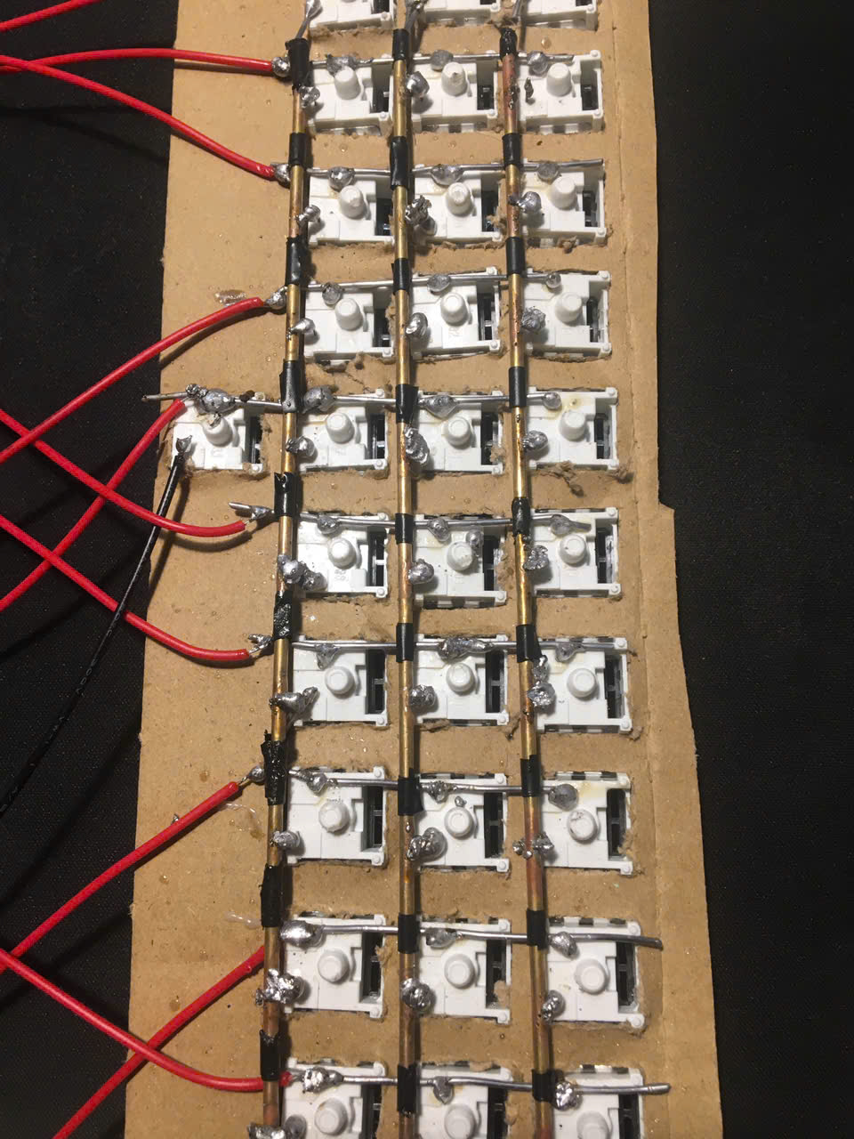
Run a wire horizontally across each row, soldering to each diode cathode. One continuous wire per row is fine — just loop, strip, solder, and continue. Keep wires tidy and close to the switches.

Pro Tip

Use one wire color for all rows and a different color for all columns.

04

Step 4 // HANDWIRING

Wire the Columns

Run a wire vertically through each column, soldering to the top pin of each switch. One wire per column. The row wires connect to diode cathodes; column wires connect directly to switch pins. These two must never touch.

05

Step 5 // HANDWIRING

Connect to Controller

Connect each row wire and each column wire to a GPIO pin on your Pro Micro. Document every connection — row N → pin X, column N → pin Y. You will need this exact mapping in your Arduino sketch. Use a consistent numbering scheme.

Pro Tip

A spreadsheet mapping matrix positions to pin names makes the Arduino sketch much faster to write.

Step 5

06

Step 6 // HANDWIRING

Flash Arduino Firmware & Validate Matrix

Open the firmware sketch in Arduino IDE. Set your matrix size and pin assignments (rowPins, colPins arrays) to match your wiring. Upload to the Pro Micro and test every key in a keyboard tester — look for missing keys or ghosting, which usually means a bad diode joint.

Pro Tip

Add Serial.println() debug output to identify dead rows/columns quickly during testing.

Join the Discussion

Stuck on a step, got a tip, or finished your build? Leave us a comment through the form — we read every one and it helps us improve the guide.

Leave a Comment →