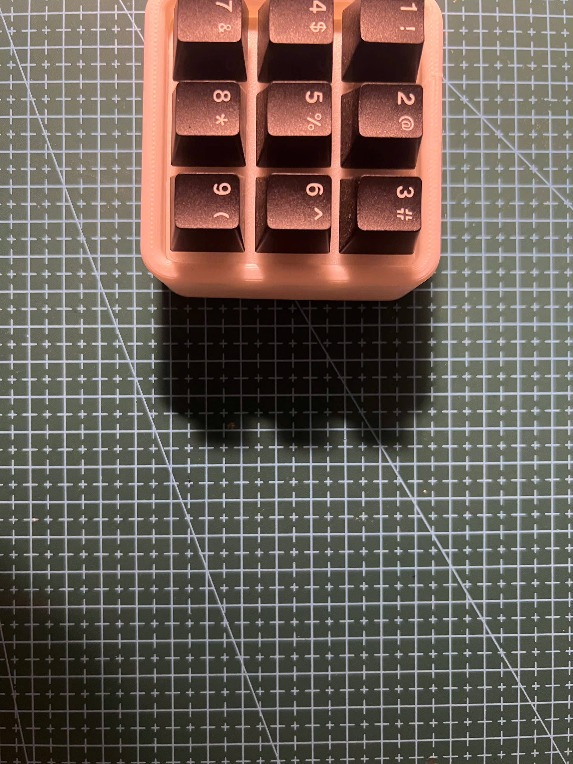
Building the MonkiiPad3x3
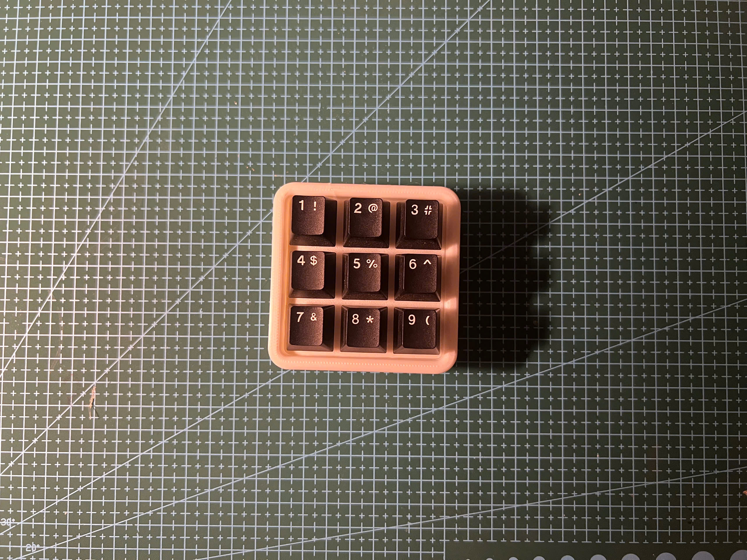
The MonkiiPad3x3 is our most beginner-friendly build. Nine switches in a 3×3 grid, fully handwired to a Pro Micro ATmega32U4. No PCB needed — just solder, wire, and a 3D-printed plate. The result is a compact, fully programmable macropad you can put to work immediately.
System Status
Nominal
Difficulty
Beginner
Build Rev.
2–3 hours
Before You Build
Gather everything below before you start — it makes the whole build go smoothly.
Component Manifest
| Component | Qty | Specification |
|---|---|---|
| MX-compatible switches | 9 | Any MX switch works |
| Pro Micro ATmega32U4 | 1 | Programmed via Arduino IDE |
| Hookup wire (24 AWG) | ~2m | Two colors recommended |
| 3D Printed Plate (STL provided) | 1 | PLA, 0.2mm layer height |
| Keycaps (1u × 9) | 9 | Any MX-compatible keycaps |
| M2 screws (4mm) | 4 | For case assembly |
| Soldering iron + solder | — | Any soldering iron works for this build |
Tools Required
01
Soldering iron
02
Solder
03
Wire strippers
04
Flush cutters
05
Tweezers
06
Computer with Arduino IDE installed
Build Steps
01
Step 1 // MONKIIPAD-3X3
Print the Plate
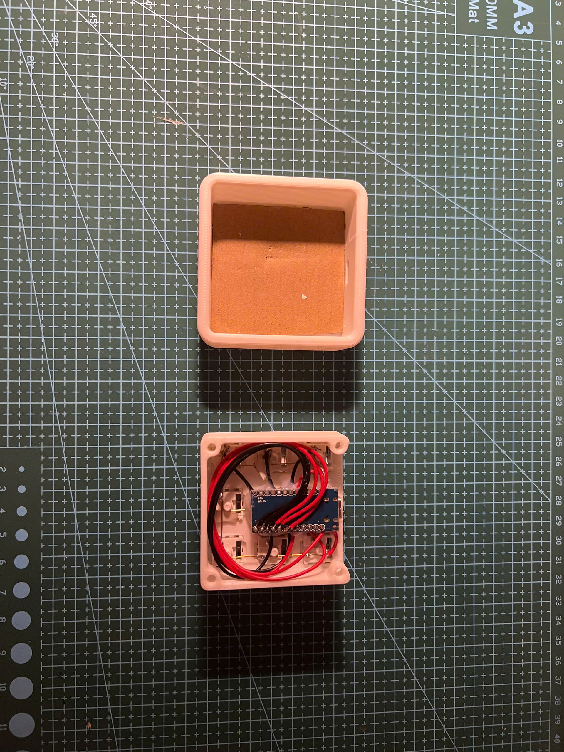
Download the MonkiiPad3x3 STL files from our GitHub and 3D print the plate and bottom shell in PLA. Use 0.2mm layer height, 20% infill. No supports needed. The plate has nine switch cutouts in a perfect 3×3 grid.
02
Step 2 // MONKIIPAD-3X3
Mount the Switches
Snap all 9 switches into the plate — they should click in firmly with no wobble. The MonkiiPad3x3 is a diodeless matrix, so there are no diodes to add: each switch wires straight into the row/column grid.
Pro Tip
Check that no switch pins are bent before pressing them in — bent pins cause hard-to-trace matrix issues.
03
Step 3 // MONKIIPAD-3X3
Wire the Rows
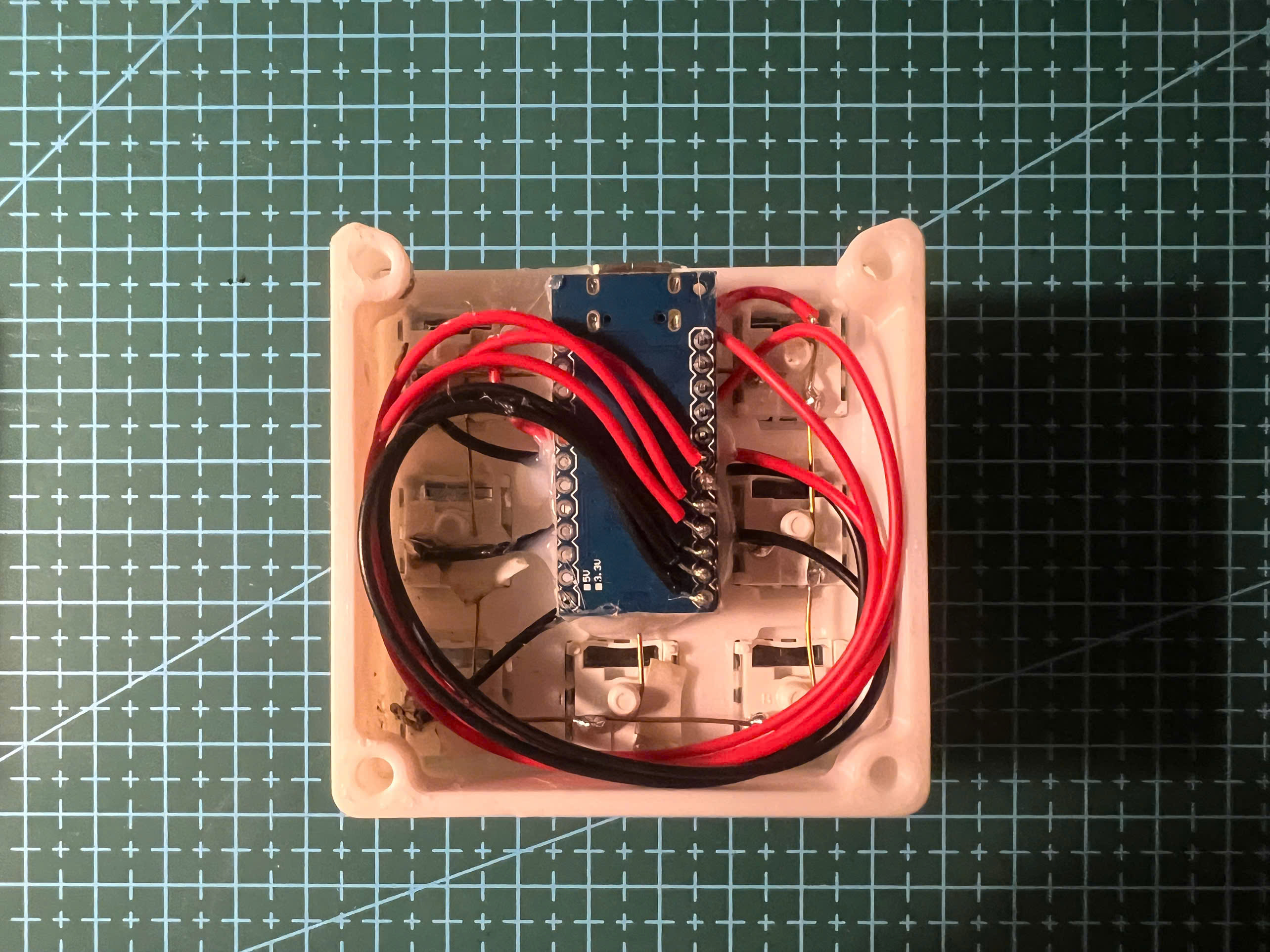
Run a wire across each of the 3 rows, soldering directly to one pin of each switch in that row. Strip a small window at each joint, solder, and move to the next. Three rows = three wires.
Pro Tip
Use one color for row wires and another for column wires to avoid confusion.
04
Step 4 // MONKIIPAD-3X3
Wire the Columns
Run a wire down each of the 3 columns, soldering to the top pin of each switch. Three columns = three wires. These must never touch the row wires.
05
Step 5 // MONKIIPAD-3X3
Connect to Pro Micro & Assemble
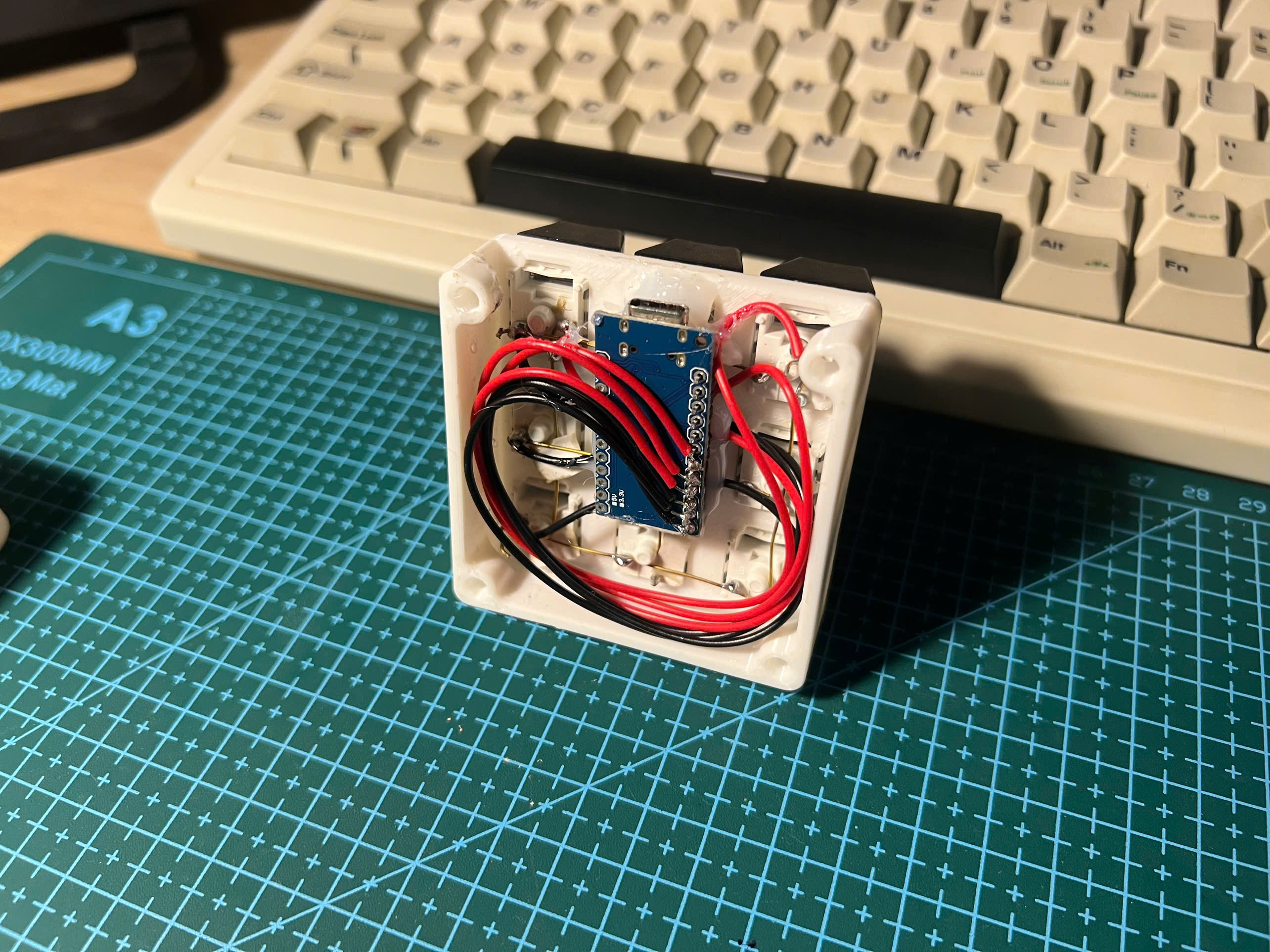
Connect each of the 3 row wires and 3 column wires to GPIO pins on the Pro Micro — the reference firmware uses rows on pins 7, 8, 9 and columns on 4, 5, 6. Note down every connection, tuck the wiring neatly, place the assembly into the shell, and secure with M2 screws. Press keycaps onto the switches.
06
Step 6 // MONKIIPAD-3X3
Flash Arduino Firmware & Test
Open the MonkiiPad3x3 firmware sketch in the Arduino IDE. Set the rowPins and colPins arrays to match your wiring, then upload to the Pro Micro. Open a keyboard tester — all 9 keys should register. Hold key 1 for ~1.5s to toggle between number mode and macro mode (arrows, copy/paste, delete).
Pro Tip
Install the Arduino keyboard HID library before compiling — the sketch depends on it.
Firmware
The full Arduino sketch for this build. Open it in the Arduino IDE, match the pins to your wiring, and upload — or grab the whole repo from GitHub.
#include <Keyboard.h>
const int colPins[3] = {4, 5, 6};
const int rowPins[3] = {7, 8, 9};
bool macroMode = false;
unsigned long pressStart = 0;
const unsigned long holdTime = 1500;
void setup() {
for (int c = 0; c < 3; c++) {
pinMode(colPins[c], INPUT_PULLUP);
}
for (int r = 0; r < 3; r++) {
pinMode(rowPins[r], OUTPUT);
digitalWrite(rowPins[r], HIGH);
}
Keyboard.begin();
}
void loop() {
for (int r = 0; r < 3; r++) {
digitalWrite(rowPins[r], LOW);
delayMicroseconds(30);
for (int c = 0; c < 3; c++) {
if (digitalRead(colPins[c]) == LOW) {
// SPECIAL LOGIC FOR KEY 1
if (r == 0 && c == 0) {
pressStart = millis();
while (digitalRead(colPins[c]) == LOW) {
if (millis() - pressStart > holdTime) {
macroMode = !macroMode;
while (digitalRead(colPins[c]) == LOW);
delay(200);
goto skipKey;
}
}
// short press
Keyboard.write('1');
delay(20);
goto skipKey;
}
// NORMAL MODE
if (!macroMode) {
char numbers[3][3] = {
{'1','2','3'},
{'4','5','6'},
{'7','8','9'}
};
Keyboard.write(numbers[r][c]);
}
// MACRO MODE
else {
if (r == 0 && c == 1) Keyboard.write(KEY_UP_ARROW);
else if (r == 1 && c == 0) Keyboard.write(KEY_LEFT_ARROW);
else if (r == 1 && c == 1) Keyboard.write(KEY_DOWN_ARROW);
else if (r == 1 && c == 2) Keyboard.write(KEY_RIGHT_ARROW);
else if (r == 2 && c == 0) { // Ctrl+C
Keyboard.press(KEY_LEFT_CTRL);
Keyboard.press('z');
delay(10);
Keyboard.releaseAll();
}
else if (r == 2 && c == 1) { // Ctrl+V
Keyboard.press(KEY_LEFT_CTRL);
Keyboard.press('y');
delay(10);
Keyboard.releaseAll();
}
else if (r == 2 && c == 2) { // Delete
Keyboard.write(KEY_DELETE);
}
else {
Keyboard.write('1');
}
}
while (digitalRead(colPins[c]) == LOW);
delay(20);
skipKey:;
}
}
digitalWrite(rowPins[r], HIGH);
}
}
Join the Discussion
Stuck on a step, got a tip, or finished your build? Leave us a comment through the form — we read every one and it helps us improve the guide.
Leave a Comment →