Deep-Dive Series // 5 Steps

Fixing a Dead Key

A short diagnostic for when one key refuses to type

Difficulty

Beginner

Time

20 minutes

Steps

5 stages

Every file for this build is up on GitHub, the plates, the case and the firmware

Our GitHub

Before You Build

Gather everything below before you start and the whole build goes a lot smoother. The printable parts are on GitHub, so you only need to buy the hardware.

Component Manifest

Component Qty Specification
Multimeter with continuity mode 1 The cheapest one will do. This is the tool that finds the fault
Soldering iron 1 For whatever you find

Tools Required

01

Multimeter

02

Soldering iron

03

Good light

04

A keyboard tester in the browser

Build Steps

Work through these in order. Anything you need to download along the way, the plates, the case and the firmware, is already waiting for you on GitHub.

01

Step 1 of 5

Find the pattern first

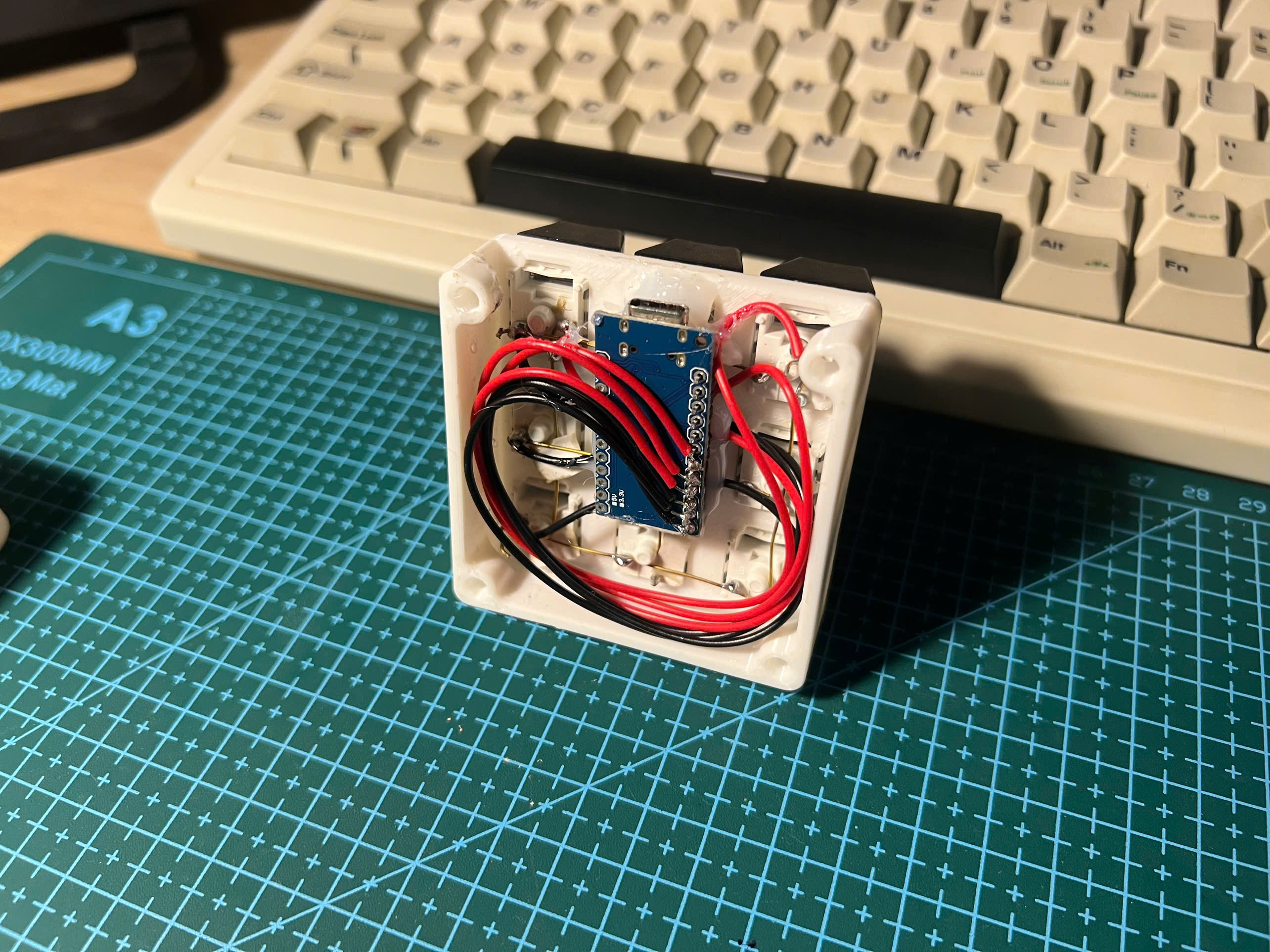
Before you open anything, press every key and write down which ones fail. One dead key is a joint or a diode. A whole dead row or column is one wire or one MCU pin. Everything dead is power or firmware. Five minutes here tells you which of the next steps to jump to, and saves you inspecting sixty joints for no reason.
Find the pattern first
Step 1, Find the pattern first

02

Step 2 of 5

Look at the joint before you test it

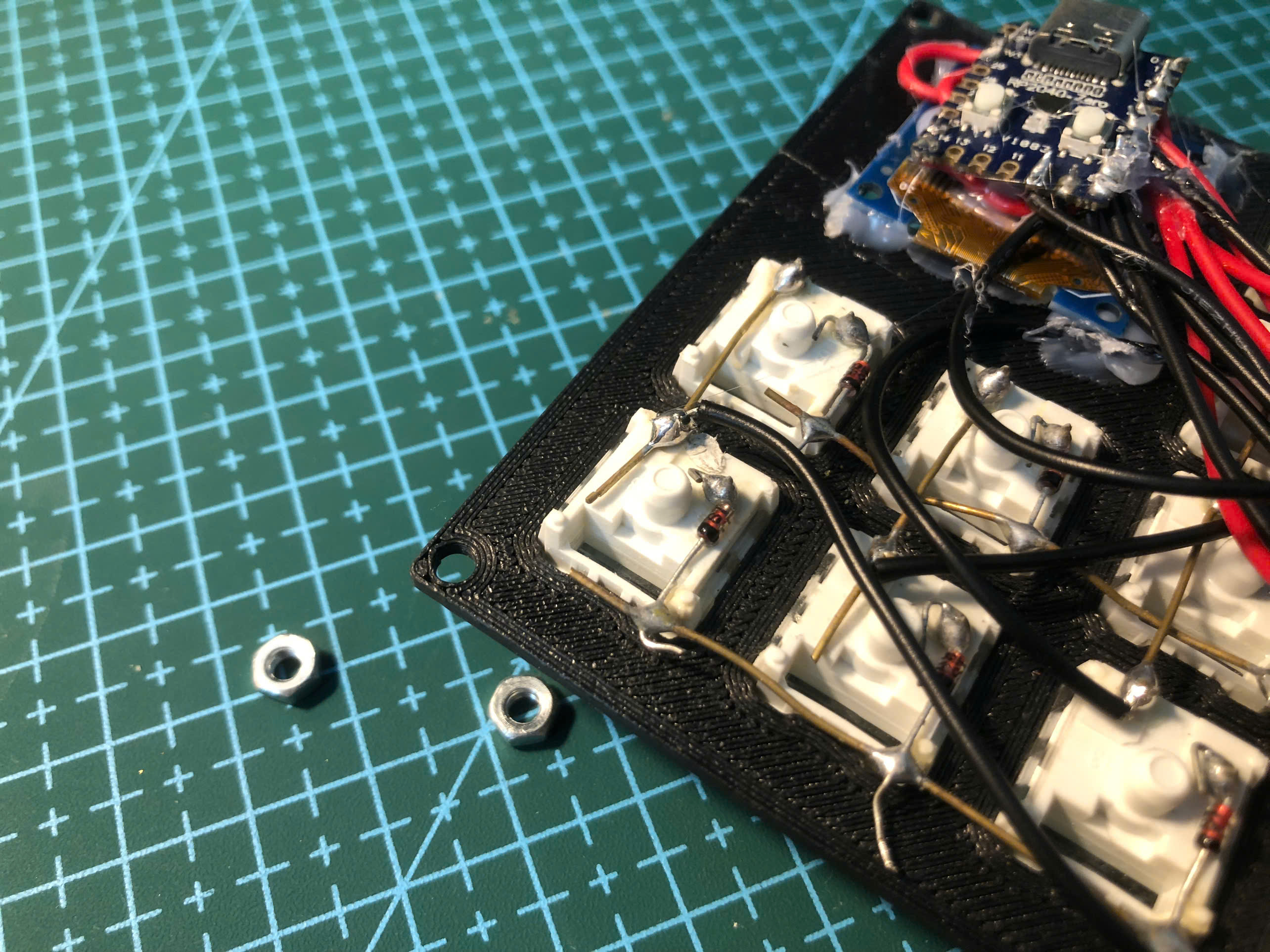
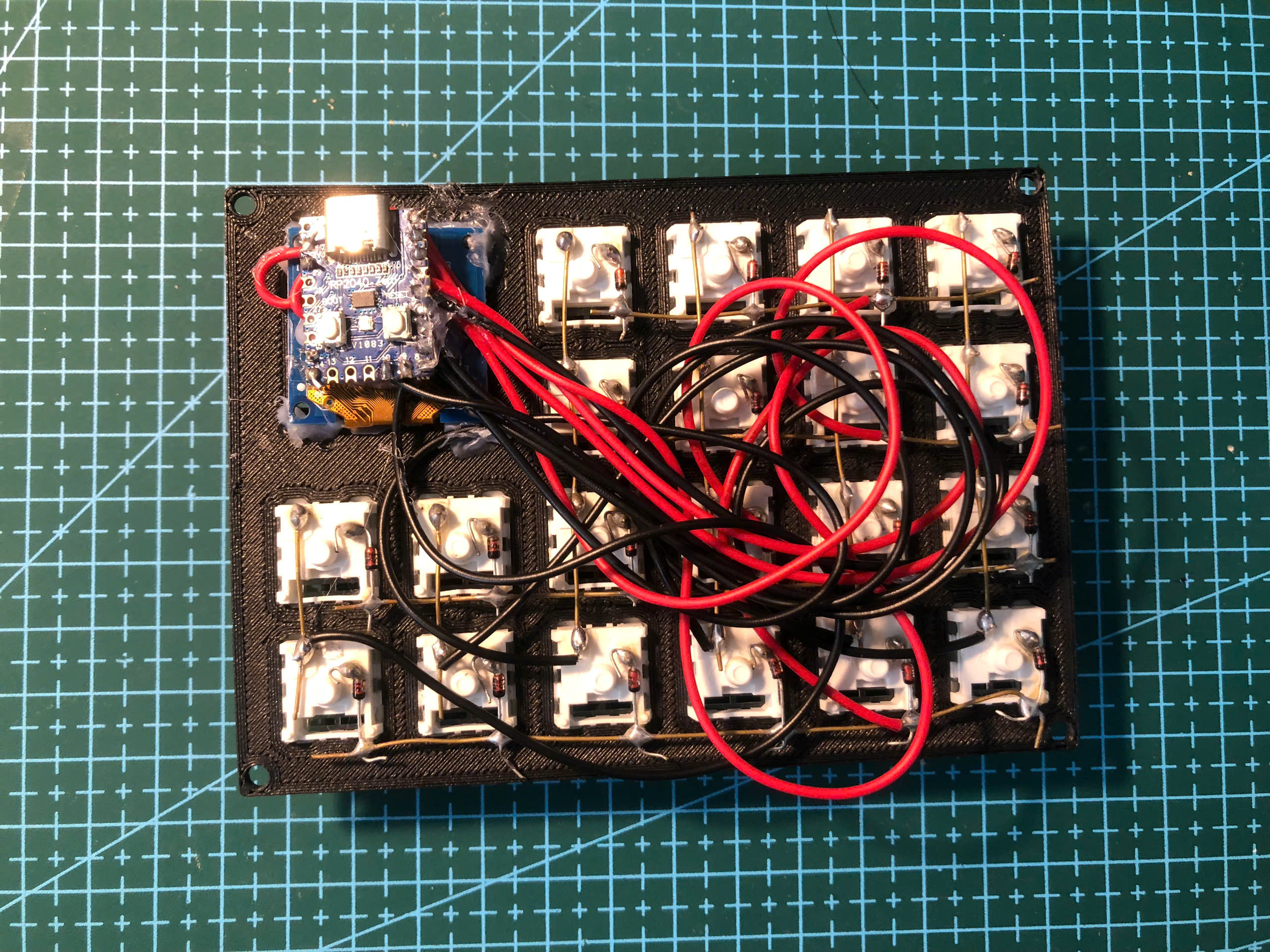
Open the sandwich and put a light on the suspect switch. You are looking for a joint that is dull rather than shiny, a wire that is resting against a pad without being soldered to it, or a strand that has wandered across to a neighbour. A surprising number of dead keys are visible before you ever pick up a meter.

Pro Tip

Reheating a suspect joint and adding a touch of fresh solder takes ten seconds and fixes this more often than it has any right to.

Look at the joint before you test it
Step 2, Look at the joint before you test it

03

Step 3 of 5

Check the diode direction

If your board has diodes, put the meter in continuity mode across one. It should beep in one direction only. A diode in backwards gives you exactly this symptom, one key that never reports while its neighbours are fine, and it is easy to do when you are placing dozens of them. The band on the diode body is the cathode and it faces the row wire.

Pro Tip

Compare against a key that works rather than trying to remember which way round is correct. The working one is your reference.

Check the diode direction
Step 3, Check the diode direction

04

Step 4 of 5

Trace the row and the column

Still nothing? Put one probe on the MCU pin for that key's row and the other on the switch leg, and press the key. No beep means the break is somewhere along that wire. Repeat for the column. This finds breaks hiding under insulation, which you cannot see, and it is why the meter is worth owning.

Trace the row and the column
Step 4, Trace the row and the column

05

Step 5 of 5

Rule out the firmware last

If the hardware tests clean, the key may simply not be mapped. Open your sketch and check that position actually has a keycode rather than NONE, and that your rowPins and colPins match the pins you soldered to. Rebuilding the layout in the Keymap Editor and reflashing is the quickest way to rule this out.

Pro Tip

Still stuck after all five? Send us a photo through the comment form. We have almost certainly made the same mistake ourselves.

Rule out the firmware last
Step 5, Rule out the firmware last

Join the Discussion

Stuck on a step, got a tip, or just finished your build? Drop it in our form. We read every single one and it helps us make the guide better.

Leave a Comment →